[ad_1]
We start by synthesizing single crystals of R/S-NEAPbI3 chiral lead halide perovskites utilizing a sluggish cooling technique21,22,23. Powder X-ray diffraction sample of the crystals are per literature22 (Supplementary Fig. 1) and present the absence of impurities. Determine 1b reveals the crystal construction of 1D S-NEAPbI3 chiral lead halide perovskite24. The hybrid organic-inorganic materials consists of inorganic 1D chains of face-sharing lead halide octahedra surrounded by natural chiral ligands S-(-)-1-(1-naphthylammine). The natural chiral ligands type uneven hydrogen bonds with the inorganic framework and have been reported to switch chirality by way of helical structural distortions22 and uneven digital interactions25. Compared to 2D chiral perovskites, the place chiral ligands are situated between 2D lead-halide sheets, the 1D chiral perovskites present a stronger chiroptical exercise as a result of the chiral ligands surrounding the lead-halide chains result in a stronger distortion within the later methods26,27. The round dichroism (CD) spectra of spin forged skinny movies of R- and S-NEAPbI3 in Fig. 1c present sturdy CD alerts, with peaks showing on the similar power, however with reverse indicators for the 2 enantiomers. This confirms their choice for absorption of sunshine with reverse helicities. The bisignate sign at about 3.2 eV corresponds to exciton absorption (Supplementary Fig. 2) and is in settlement with literature26.
Weak van der Waals interactions between the natural ligands permits the chiral perovskite crystals to be mechanically exfoliated into skinny flakes with easy surfaces28,29,30 (affirmation by atomic drive microscopy (AFM) in Supplementary Fig. 3). To make heterostructures, MoS2 flakes had been mechanically exfoliated on Si/SiO2 substrate and monolayers had been recognized utilizing AFM and Raman micro-spectroscopy (Supplementary Fig. 4). Subsequent, chiral perovskite flakes roughly 500 nm thick had been stacked on high of the monolayer MoS2 utilizing a dry switch technique31. Digital power bands measured utilizing ultraviolet photoelectron spectroscopy (UPS) present that the chiral perovskites have a valence band maxima at −7.7 eV relative to the vacuum degree (Supplementary Fig. 5). Contemplating a bandgap of three.3 eV estimated from the UV-Vis absorption information (Supplementary Fig. 2), the conduction band minima is at about −4.4 eV relative to the vacuum degree, which offers a sort II (staggered) power band alignment between the perovskite and monolayer MoS2 (Fig. 1d).
Photoluminescence measurements
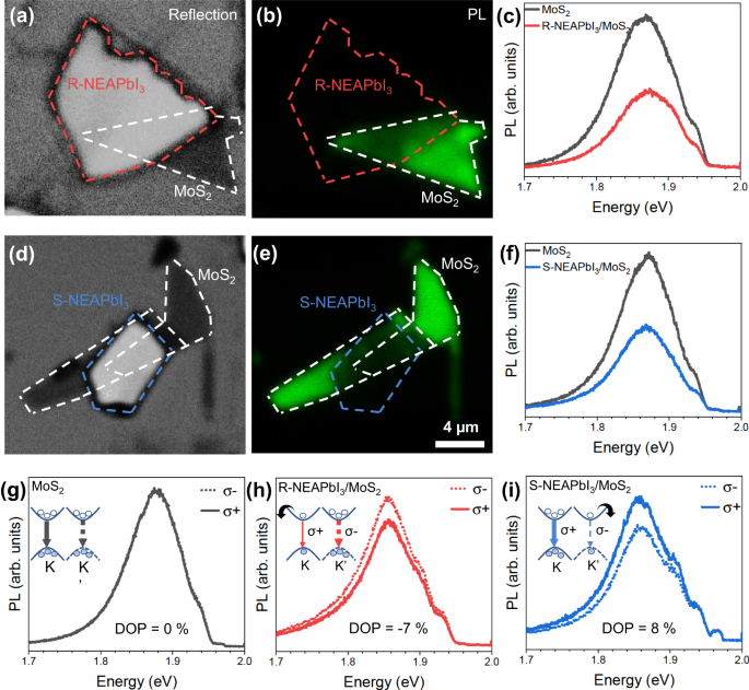
We optically excited the heterostructure with a linearly polarized laser of 1.96 eV power and measured the emitted photoluminescence (PL) in a confocal microscope (see “Strategies” for particulars). Because the chiral perovskite has a bandgap of three.3 eV (Supplementary Fig. 2), we anticipate negligible absorption of the laser mild by this element of the heterostructure. Determine 2a, b reveals the reflection and PL maps of a R-NEAPbI3/MoS2 heterostructure, the place white and pink sprint strains define the monolayer MoS2 and the chiral perovskite flake R-NEAPbI3, respectively. The overlap area of the heterostructure demonstrates a quenched PL sign compared to the pristine monolayer MoS2 area. The PL spectra in Fig. 2c reveals that each monolayer MoS2 area and the overlap area of the heterostructure have peaks at 1.86 eV, which we relate to the A-exciton optical transition from the conduction band to the higher break up valence band in MoS2. Nonetheless, the PL spectrum from the overlap area is way decrease in depth. We obtained comparable outcomes additionally for the S-NEAPbI3/MoS2 heterostructure that are proven in Fig. second–f. Though there may be some variation within the depth of PL emission from level to level on a pattern, the PL from the overlap areas is quenched, on common, 50% compared to the pristine monolayer area. Wanting on the kind II power band alignment of the heterostructure elements proven in Fig. 1d, photoinduced electron switch is predicted to happen from the conduction band of the photo-excited monolayer MoS2 to R-NEAPbI3. This photoinduced cost switch competes with radiative recombination in MoS2, leading to a quenched PL of MoS2. Emission at low power from interlayer excitons, which have been reported in TMD/2D perovskite heterostructures20,34, was absent within the spectral vary probed (1.3–2 eV). Subsequently, on this work we deal with solely MoS2 emission.
a Optical reflection picture and b PL map of R-NEAPbI3/MoS2 heterostructure. c PL spectra from MoS2 solely area (black) and overlap area (pink) of R-NEAPbI3/MoS2 heterostructure. d Optical reflection picture and e PL map of S-NEAPbI3/MoS2 heterostructure. f PL spectra from monolayer MoS2 solely area (black) and overlap area (blue) of S-NEAPbI3/MoS2 heterostructure. The dotted white, pink, and blue strains define the monolayer MoS2, R-NEAPbI3 flake and S-NEAPbI3 flake, respectively. Polarization resolved PL spectra of g monolayer MoS2, h R-NEAPbI3/MoS2, and i S-NEAPbI3/MoS2. The strong strains and dotted strains present left (σ+) and proper (σ−) circularly polarized elements of the PL, respectively. The inset reveals schematics of digital bands at Okay and Okay′ valley with respective optical choice guidelines. The arrows point out preferential electron switch from particular valleys in MoS2 to R- and S-NEAPbI3 chiral perovskite, respectively. Electrons and holes are depicted as empty and stuffed circles.
The polarization resolved PL sign of monolayer MoS2 (Fig. 2g) reveals that the left (σ+) and proper (σ−) circularly polarized elements of the PL spectrum are an identical in peak place, form, in addition to depth. The R-NEAPbI3/MoS2 heterostructure (Fig. 2h), nevertheless, has a better PL emission peak depth for σ− (dotted line), whereas the S-NEAPbI3/MoS2 heterostructure (Fig. 2i) has a better PL emission peak depth for σ+ (strong line). As a result of we optically pump each Okay and Okay′ valleys equally with a linearly polarized mild, for monolayer MoS2, the PL emitted ensuing from radiative recombination from the Okay and Okay′ valleys is predicted to be comparable, as noticed right here in Fig. 2g. The PL emission variations noticed for the heterostructures may be defined considering the digital band construction of MoS2 (Fig. 1a), the place spin–orbit coupling splits the valence band maxima into two bands separated by about 150 meV3. Excitation with the 1.96 eV laser mild promotes electrons solely from the higher spin break up valence band, related to the A-exciton, and this populates the conduction band with spin up electrons within the Okay valley and spin down electrons within the Okay′ valley. The photo-excited electrons within the conduction band of MoS2 are then pushed by the sort II (staggered) heterostructure to the conduction band of chiral perovskite (Fig. 1d). Nonetheless, right here the chiral perovskite acts as a spin filter: R-NEAPbI3 preferentially accepts spin up electrons, whereas S-NEAPbI3 preferentially accepts spin down electrons. This creates a inhabitants imbalance within the two valleys, leading to a better σ− PL emission depth within the R-NEAPbI3/MoS2 heterostructures and vice versa within the S-NEAPbI3/MoS2 heterostructures (as proven in insets in Fig. 2h-i). Within the overlap area with bilayers MoS2 in Fig. 2e, we observe negligible distinction between σ+ and σ− PL emission (Supplementary Fig. 6). That is anticipated for the reason that inversion symmetry is preserved in bilayers and due to this fact spin and valley aren’t coupled6.
To quantify the chirality of the PL emission, we use the diploma of polarization (DOP) outlined as:
$${DOP}=frac{Ileft(sigma+proper)-Ileft(sigma -right)}{Ileft(sigma+proper)+Ileft(sigma -right)}*100%$$
(1)
the place I(σ+) and I(σ−) are the height intensities of left and proper round polarized elements of the PL emission, respectively. The DOP for monolayer MoS2, R-NEAPbI3/MoS2, and S-NEAPbI3/MoS2 are 0%, −7%, and eight%, respectively. A worth of DOP of 0% obtained for monolayer MoS2 confirms that artifacts attributable to distinction in transmission of σ+ and σ− of optical elements of the confocal setup, comparable to mirrors and lenses, are negligible and validates our measurements. In Supplementary Fig. 7, we present PL measured at completely different laser intensities for a set of R-NEAPbI3/MoS2 and S-NEAPbI3/MoS2 heterostructures which additionally confirmed DOP of −5 ± 1% and 6 ± 2%, respectively. Heterostructures transferred on hBN additionally demonstrated a DOP of −6%, confirming that the substrate doesn’t have an effect on the DOP (Supplementary Fig. 8). Time-dependent PL measurements (Supplementary Figs. 9, 10) present that the noticed phenomenon can be secure over time.
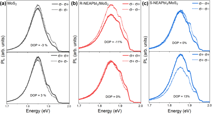
Through the use of circularly polarized excitation we may additional improve the DOP. Determine 3 reveals PL measurements carried out with circularly polarized 1.96 eV laser. For MoS2 monolayer, we obtained DOP of −3% and three% for excitation with σ− and σ+, respectively. The DOP of R-NEAPbI3/MoS2 heterostructure was −11% for σ− excitation and 0% for σ+ excitation. Equally, the DOP of S-NEAPbI3/MoS2 heterostructure was 0% and 13% for σ− and σ+ excitation, respectively. These outcomes are additionally per spin selective electron switch from MoS2 to chiral perovskite. In naked monolayer MoS2, the emission is larger when the polarization of excitation and detection are the identical (σ+σ+ or σ−σ−) compared to the case when they’re reverse (σ−σ+ or σ+σ−), as we pump and probe the identical valley within the former case4,5,6,7,8. The DOP for σ+ and σ− excitation even have the identical magnitude however reverse signal for the reason that two valleys are symmetric. In R-NEAPbI3/MoS2 heterostructure, nevertheless, when Okay′ valley is selectively excited by σ−, σ+ emission from Okay valley is additional diminished attributable to preferential switch of spin up electrons from Okay valley to R-NEAPbI3. Subsequently, the DOP for σ−(σ+) excitation is additional enhanced whereas that for σ+(σ−) excitation is diminished in R-NEAPbI3(S-NEAPbI3)/MoS2 heterostructure compared to naked MoS2 monolayer. We notice that apart from the height at 1.86 eV, the emission seems to have an extra peak at 1.89 eV. As we noticed this sign additionally from SiO2 substrate measured below the identical circumstances, we attribute the height to scattered laser leaking in by the filters (Supplementary Figs. 11, 12).
Polarization resolved PL spectra with circularly polarized excitation of a monolayer MoS2, b R-NEAPbI3/MoS2, and c S-NEAPbI3/MoS2. The legend signifies the polarization of excitation adopted by polarization of the emission. The highest and backside plots present measurements carried out with proper (σ−) and left (σ+) circularly polarized excitation, respectively, at 1.94 eV. The strong strains and dotted strains present σ+ and σ− circularly polarized elements of the emitted PL, respectively.
The power of optical excitation is one other parameter that can be utilized to control valley polarization in these heterostructures. Determine 4 reveals polarization resolved PL spectra of the R-NEAPbI3/MoS2 heterostructure obtained with linear polarized laser excitation of 1.96 eV, 2.09 eV, and a couple of.33 eV in Fig. 4a–c, respectively. For the A-exciton transition, we noticed a DOP of −7% for the 1.96 eV laser excitation which decreased to −3% for the two.09 eV optical excitation and for a similar heterostructure pattern. Equally, no polarization, i.e., a DOP = 0%, was noticed for the two.33 eV optical excitation. These are observations per stories pointing to a decrease valley polarization below non-resonant excitation circumstances attributable to larger intervalley scattering5,35. We notice that for two.09 eV optical excitation, the noise from the scattered laser made it troublesome to entry the polarization of the B-exciton emission situated at about 2.02 eV. Nonetheless, for R-NEAPbI3/MoS2, we anticipate to watch an reverse polarization conduct for the B-exciton with 2.09 eV excitation, i.e., DOP values adverse and optimistic for A- and B-exciton transitions, respectively. It is because a linearly polarized laser with an power of two.09 eV will excite electrons from each the higher and decrease spin break up valence bands, whereas solely spin up electrons are preferentially transferred from the conduction band of monolayer MoS2 to R-NEAPbI3 within the R-NEAPbI3/MoS2 heterostructure. Resulting from valley contrasting spin splitting of valence bands, the ensuing inhabitants imbalance within the Okay and Okay′ valleys must be reverse for A and B excitons (schematic in Supplementary Fig. 13). Subsequently, by utilizing chiral perovskites as spin filters, it’s doable to concurrently populate each the Okay and Okay′ valleys with both spin up or spin down electrons. With a circularly polarized excitation, one can manipulate solely a particular valley: regardless of the power of the optical excitation, σ+(σ−) will populate solely the Okay (Okay′) valley. Nonetheless, the spin filtering technique affords the potential for utilizing excitation power as an extra parameter to control valley and spin polarization.
Helicity resolved PL spectra of R-NEAPbI3/MoS2 with a 1.96 eV (or 633 nm), b 2.09 eV (or 594 nm), and c 2.33 eV (or 532 nm) laser excitation. The strong and dotted strains present left (σ+) and proper (σ−) circularly polarized elements of the PL, respectively. The orange arrows point out the power of the laser used for optical excitation.
Transient absorption spectroscopy measurements
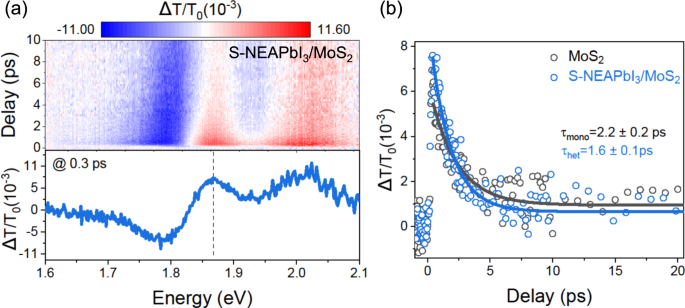
We obtained direct proof for a photoinduced cost switch within the offered heterostructures by pump-probe transient absorption spectroscopy. We optically pumped the samples at 2.48 eV (40 µJ cm−2 fluence, 200 fs pulse width) and measured the photo-induced modifications in absorption of a white mild continuum probe after a managed time delay. Determine 5a reveals the differential transmission 2D plot (high) and transient spectra at 0.3 ps delay (backside) of the MoS2/S-NEAPbI3 heterostructure, with options at 1.8 and a couple of.0 eV equivalent to the A- and B-exciton transitions of MoS2, respectively36,37,38 (Supplementary Fig. 14). The decay of the A-exciton at 1.87 eV for the heterostructure versus the monolayer MoS2 is proven in Fig. 5b. Utilizing a single exponential decay mannequin (strong strains), we obtained provider lifetimes of two.2 and 1.6 ps for the monolayer MoS2 (τmono) and for the heterostructure MoS2/S-NEAPbI3 (τHet), respectively. We attribute the shorter provider lifetime noticed within the heterostructure to electron switch from monolayer MoS2 to 1D chiral perovskite. Quicker decays attributable to ultrafast cost switch between TMDs and perovskites (as quick as 45 fs) have been beforehand reported39,40,41,42,43 from transient absorption and time-resolved PL measurements. We estimated a cost switch fee, (1/{tau }_{{{{{{{rm{CT}}}}}}}}=1/{tau }_{{{{{{{rm{Het}}}}}}}}-1/{tau }_{{{{{{{rm{mono}}}}}}}}), and a cost switch effectivity, ({Phi }_{{{{{{{rm{CT}}}}}}}}=1-{tau }_{{{{{{{rm{Het}}}}}}}}/{tau }_{{{{{{{rm{mono}}}}}}}}), of 1/5.9 ps−1 and 27%44,45.
a 2D picture of a differential transmission spectra (ΔT/T0) as a operate of probe delay. The colour bar reveals the depth of the ΔT/T0 with pink and blue indicating optimistic and adverse values, respectively. The plot on the backside reveals ΔT/T0 spectra at a delay of 0.3 ps. b Decay kinetics of monolayer MoS2 (black circles) and S-NEAPbI3/MoS2 heterostructure (blue circles) at 1.87 eV (proven by a dotted line in (a)). The strong strains are match to mono-exponential decay operate.
[ad_2]


