[ad_1]
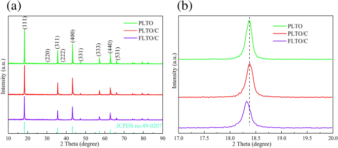
The crystal construction and section composition of the FLTO/C, PLTO and PLTO/C had been analyzed by XRD, and the outcomes are proven in Fig. 2a. Based on JCPDS 49-0207, the three LTO supplies crystallized within the F__d3m house group. No peak of Fe-containing oxide is noticed within the FLTO/C electrode materials, demonstrating that Fe doping into the LTO lattice didn’t change the construction of LTO, or that the Fe content material is low and undetected. Sometimes, when the ionic radius is near the doped metallic ion radius, the substitution response is extra prone to happen or the dopant can enter the lattice hole to type an energetic middle. The ionic radius of Fe2+ (0.78 Å)24, 25is just like these of Li+ (0.76 Å)26,27,28 and Ti4+ (0.68 Å)29,30,31. In LTO construction, Li+ occupies the tetrahedral 8(a) place or octahedral 16(c) place; its occupying place could be mirrored within the intensities of the (311) and (400) peaks. The relative energy ratio of the (311) and (400) peaks will increase with the rise in Fe content material, thus, reflecting the change within the Li+ ion place on Fe doping32, 33. The I(311)/I(400) energy ratio of the FLTO/C electrode materials is just not a lot completely different from that of the unique PLTO, indicating that Fe2+ is just not doped into the Li website. Determine 2b reveals a magnification of the XRD patterns of the three electrode supplies for the (111) crystal airplane. The height of FLTO/C shifts to a smaller angle, indicating that the Fe2+ dopant entered the Ti website, additional indicating that the carbon-coated Fe-doped LTO materials had been efficiently ready.
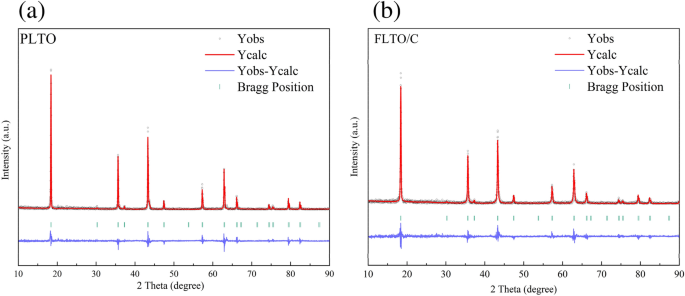
The affect of Fe doping on the LTO construction was additional examined by implementing Rietveld refinement on the Fullprof software program, to calculate the crystal dimension, as depicted in Fig. 3a,b. The lattice parameters and different related info are summarized in Desk 1. Outcomes point out that Fe substitution elevated the lattice parameters from 8.35458 to eight.35504 Å. This shift could be attributed to the bigger ionic radius of Fe2+ in comparison with Ti4+. The partial substitution of Ti4+ by Fe2+ elevated the unit cell quantity within the LTO construction. The correct Fe focus within the FLTO/C electrode materials was obtained by ICP-OES evaluation. The focus of Fe in FLTO/C was roughly 0.27%, confirming the formation of Li4Ti4.9865Fe0.135O12/C.
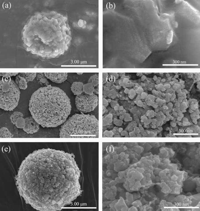
The SEM photographs of PLTO, PLTO/C and FLTO/C in Fig. 4 present LTO microspheres of about 4–5 μm diameter. Whereas the floor of the PLTO electrode materials is clean, the addition of 15% glucose roughens the floor and types small major particles and pores on the surfaces of PLTO/C and FLTO/C. This may be attributed to the addition of glucose, ensuing within the thermal decomposition of glucose throughout calcination.
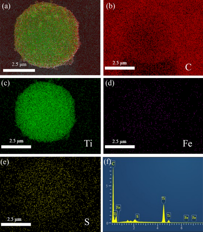
The EDS elemental mapping photographs of FLTO/C point out that Ti, C, S and Fe had been uniformly distributed within the electrode, as proven in Fig. 5. Hint quantities of floor sulfur on FLTO/C could be attributed to the residual sulfur from industrial H2TiO3, which is tough to take away throughout the washing course of. Determine 5d reveals that the distribution of Fe is in step with the distribution of Ti, O and C, indicating that Fe is uniformly distributed within the LTO crystal construction. The Fe ions are adsorbed by H2TiO3 with a powerful binding drive and good stability, which lays a basis for subsequent doping reactions and uniform distribution. In the meantime, XRD diffraction doesn’t discover the height of iron oxide, so on the idea of the above dialogue, we synthesized Fe-doped LTO/C microspheres.
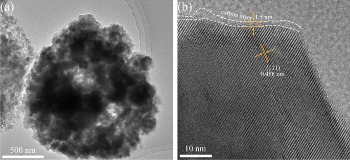
The thickness of the carbon layer and lattice distance of FLTO/C had been assessed utilizing HRTEM (Fig. 6). The FLTO/C electrode materials reveals a fairly uniform carbon layer with a thickness of roughly 1.5 nm. The (111) crystal airplane of FLTO/C corresponds to a crystal airplane spacing of 0.488 nm, whereas that of pure section LTO is about 0.483 nm34. These outcomes verify that introducing Fe2+ into the LTO lattice will increase the LTO lattice fixed, aligning with the XRD outcomes. An expanded crystal face spacing promotes the diffusion of Li+ culminating in higher electrochemical efficiency of LTO.
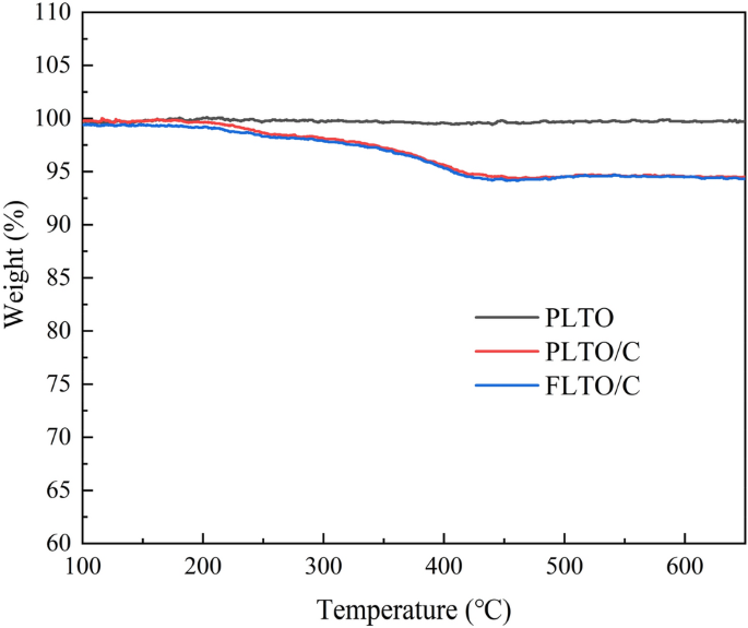
TGA evaluation was used to indicate the connection of weight reduction with the temperature enhance, as proven in Fig. 7. The thermal decomposition temperature of carbon is about 270–400 °C, and the mass loss signifies the coating ratio of carbon within the composite. As well as, TGA check of PLTO was additionally carried out to make sure the accuracy of the conclusions. Due to this fact, based mostly on the outcomes of PLTO, PLTO/C and FLTO/C, it may be calculated that the carbon content material in FLTO/C and PLTO/C is about 2.81 wt% and a couple of.77 wt%.
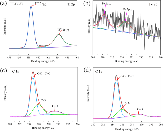
XPS was used to research the chemical state of Ti, C and Fe in FLTO/C, as proven in Fig. 8. The Ti 2p peaks could be assigned to Ti 2p1/2 (464.25 eV) and Ti 2p3/2 (458.5 eV)35, 36, similar to Ti4+ (Fig. 8a). Determine 8b reveals the Fe 2p1/2 and Fe 2p3/2 peaks at 722.44 eV and 710.51 eV, respectively, indicating the presence of Fe2+37, 38. Determine 8c,d reveals the outcomes of FLTO/C and PLTO/C after C1s partial peak becoming. Your entire spectrum could be divided into three peaks, i.e., C–C and C=C close to 284.8 eV, C–O at 285.9 eV, and C=O at 289.3 eV39,40,41. It’s recommended that, when Fe is doped into the LTO lattice, the valence state and composition of C don’t change.
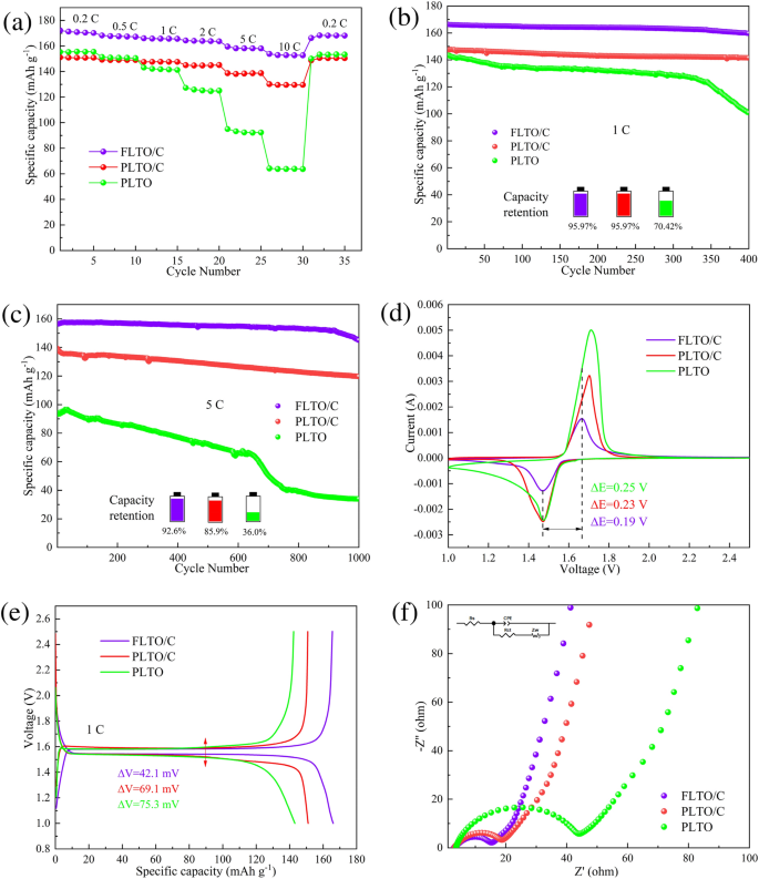
Half-cells had been assembled utilizing dual-modified FLTO/C composites because the energetic materials and PLTO and PLTO/C because the management samples. Determine 9a reveals the speed efficiency of PLTO, PLTO/C and FLTO/C, at present densities starting from 1 to 10 C. At 0.2 C, 0.5 C, 1 C, 2 C, 5 C and 10 C, FLTO/C confirmed discharge capacities of 172.15, 168.21, 166.02, 164.27, 159.50, and 153.79 mAh g−1, respectively, considerably exceeding these of PLTO and PLTO/C as summarized in Desk S1. These outcomes present that FLTO/C has the next particular capability than 150 mAh g−1 over 2–10 C, considerably surpassing the restrictions of upper price efficiency of PLTO and PLTO/C.
The biking efficiency of PLTO, PLTO/C and FLTO/C had been examined at a present density of 1 C, as proven in Fig. 9b. After 400 cycles, the capability retention charges of PLTO, PLTO/C and FLTO/C had been 70.42%, 95.97% and 95.97%, respectively. Determine 9c illustrates the cost and discharge cycles at 5 C for PLTO, PLTO/C, and FLTO/C after 1000 cycles. The long-term biking stability of PLTO and PLTO/C reveals preliminary discharge capacities of 94.29 and 139.27 mAh g−1, respectively. After 1000 cycles, the capability retention charges of PLTO and PLTO/C lower to 35.99% and 85.91%, respectively, whereas their discharge capacities drop to 33.94 and 119.65 mAh g−1, respectively. After 1000 cycles at 5 C, FLTO/C displays an preliminary and residual particular capability of 156.62 and 145.02 mAh g−1, respectively, with a corresponding capability retention price of 92.56% and an ultra-low capability decay price of 0.007% per cycle.
The above outcomes present that as a result of twin modification by Fe doping and carbon coating, the particular capability and stability of LTO present dramatic enchancment. This habits could be defined as follows; when a certain quantity of carbon is added, the floor of the ready FLTO/C microspheres turns into coarser, resulting in a bigger particular floor space, and the floor holes develop into extra apparent. The rise of those holes can additional facilitate Li+ to move by means of shortly. Furthermore, after Fe doping, the cell parameters and cell quantity of FLTO/C enhance, which is conducive to the diffusion of Li+ and additional improves the digital conductivity34. Due to this fact, the mixed modifications lead to wonderful price efficiency and biking stability, significantly in FLTO/C.
FLTO/C additionally demonstrates superior price and biking efficiency in comparison with management samples PLTO and PLTO/C, and different LTO composite supplies and graphite supplies, as proven in Desk 2.
CV was used to additional research the kinetic habits of the electrodes throughout the lithiation/de-lithiation course of. Determine 9d reveals the CV curves of PLTO, PLTO/C and FLTO/C at a sweep price of 0.5 mV s−1 after 100 cycles, at 1 C. The proximity of the redox peak of FLTO, to that of PLTO, and the dearth of heterodox peaks signifies that Fe doping doesn’t alter the electrochemical response of the LTO substrate materials. The height separation values of PLTO, PLTO/C and electrode had been 0.24 V and 0.23 V respectively, whereas the height separation worth of FLTO/C anode was the narrowest, solely 0.19 V, so FLTO/C confirmed the smallest polarizability. Determine 9e shows the cost–discharge plateaus of the three electrode supplies at 1 C. In contrast with PLTO and PLTO/C, FLTO/C confirmed a barely larger discharge voltage, the biggest particular capability and the smallest cost–discharge voltage distinction (42.1 mV), which is in step with the CV outcomes.
The electrochemical habits of the electrodes was studied by means of EIS and fitted to equal circuit fashions utilizing the Z-view software program, as proven in Fig. 9f. Rs represents the entire resistance of the electrolyte, separator, and fluid collector, Rct represents the cost switch resistance, CPE represents a relentless section ingredient, and Zw represents the Warburg impedance, which correlates to the Li+ diffusion course of. Determine S1 reveals the impedance velocity (Z′ diagonal) of ω−1/2 for PLTO, PLTO/C, and FLTO/C. The becoming outcomes (Desk S2) and calculations for the Li+ diffusion coefficient (Equations S1 and S2) point out that the entire resistance (Rs) values for PLTO, PLTO/C, and FLTO/C are 3.765, 3.323, and three.175 Ω, respectively. As well as, the cost switch resistance (Rct) for PLTO, PLTO/C, and FLTO/C are 35.34, 12.72, and 10.90 Ω, respectively. The calculated Li+ diffusion coefficients for PLTO, PLTO/C, and FLTO/C are 6.41 × 10⁻¹⁵, 9.45 × 10⁻¹⁴ and 5.95 × 10⁻¹³ cm2 s−1, respectively. In contrast with the PLTO and PLTO/C electrode supplies, the Li+ diffusion coefficient of FLTO/C elevated by 1–2 orders of magnitude. Thus, the twin modification by Fe doping and carbon coating considerably enhanced the FLTO/C Li+ diffusion coefficients.
A four-point probe resistivity tester confirmed that the digital conductivities of PLTO/C and FLTO/C had been 2.15 × 10⁻⁴ and eight.50 × 10−3 S cm−1, respectively. In contrast with the intrinsic conductivity of LTO, the digital conductivities of the 2 electrode supplies had considerably improved. These outcomes display that the dual-modified LTO reveals a significantly enhanced electrical conductivity. This enchancment could be attributed primarily to the carbon coating on the floor of LTO. Furthermore, the addition of Fe leads to a rise within the unit cell dimension, which promotes the migration of electrons.
[ad_2]
